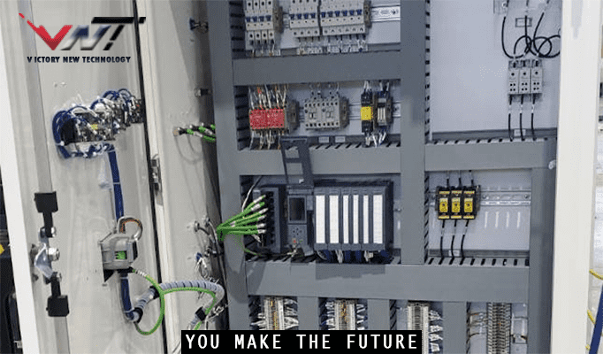
Electricity switching control systems are basically used for supplying energy efficiently to a given load in building automation applications. The integration of the main power supply with solar power supply and diesel generator power supply is a key element in designing the electricity supply switching control.
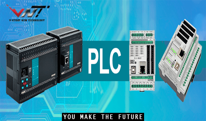
Control circuits using PLCs (Programmable Logic Controllers) are widely used in industrial automation to control and monitor various processes and equipment. PLCs are programmable electronic devices designed to execute specific control functions based on the inputs they receive and the programmed logic instructions.
Here are the key steps involved in setting up control circuits using PLCs:
1-Define the Control Requirements: Identify the specific control requirements of the system or process you want to automate. Determine the inputs (sensors, switches, etc.) that will provide information about the system’s state and the outputs (actuators, relays, etc.) that will control the system’s operation.
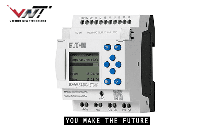
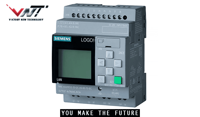
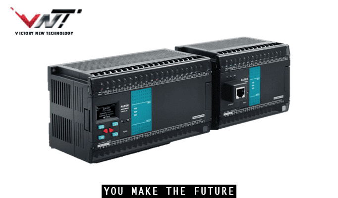
2-Select the Appropriate PLC: Choose a PLC model that meets the requirements of your control system, considering factors such as the number of inputs and outputs required, communication capabilities, processing power, and programming language support.
3-Design the Control Circuit: Create a control circuit diagram that represents the connection between the inputs, outputs, and the PLC. This diagram defines the logical relationships and interconnections between components in the system.
4-Program the PLC: Use the programming software provided by the PLC manufacturer to write the control program. PLC programming languages, such as ladder logic, function block diagrams (FBD), or structured text, are used to define the control logic and sequence of operations. The program should incorporate the desired control algorithms, input/output handling, and any necessary safety interlocks.
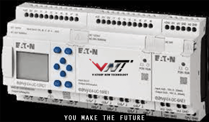
5-Configure Input/Output Modules: Configure the input and output modules of the PLC according to the specific requirements of your control system. This involves assigning input and output addresses in the PLC memory, setting up signal conditioning, and establishing communication between the PLC and external devices.
6-Test and Debug: Once the program and hardware are set up, test the control circuit by simulating or connecting the actual inputs and outputs. Verify that the control logic operates as intended, and troubleshoot any issues or errors that may arise.
7-Monitor and Maintain: Once the control circuit is operational, regularly monitor its performance and make any necessary adjustments or modifications to optimize the system’s operation. PLCs often offer diagnostic capabilities and logging features, which can help in troubleshooting and identifying potential issues.
It’s important to note that the specific steps and procedures for setting up control circuits using PLCs can vary depending on the PLC model, manufacturer, and the complexity of the control system. It’s recommended to refer to the documentation and guidelines provided by the PLC manufacturer and consult with experienced PLC engineers or automation specialists for assistance in designing and implementing control circuits using PLCs.